


Tutorial · Architect 3D 26 for Windows
How to create an elevation drawing with Architect 3D
Updated · About 5 minutes
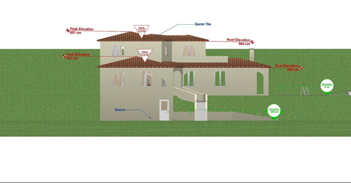
Written for Architect 3D 26 for Windows. The Mac edition has similar tools, though some menu names differ.
An elevation shows the finished appearance of one side of a building. A set of permit drawings usually needs four, one per side, and more if the building has walls that are not at right angles to each other. What each elevation must show depends on the requirements where you build.
Complete the rest of the project first: floor plans, roofs, doors and windows. The elevations are drawn from the 3D model.
Step 1: Open Elevation View and choose a side
- Click the Elevation View icon in the view toolset. You can also use Window > Elevation View, or right-click with nothing selected and choose Elevation View.
- The front elevation is shown first. Choose Back, Left or Right from the predefined views to see the other sides.
- For a façade that is not square to the others, click the Rotate Elevation View Angle tool and drag in the view to turn the building to any angle.
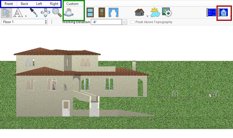
You can still edit roofs, decks and 3D objects, and place doors and windows, while you are in Elevation View.
Step 2: Annotate the elevation
Add the information the drawing needs with the text and dimension tools:
- Rich Text for titles, labels and text boxes.
- The dimension tools for heights, widths and any other measurement.
- Leader Dimension to point at an element and attach a note to it.
- Callout to mark sections or ground levels.
- Note for notes in different shapes and styles.
- Marker Line to show floor levels, heights and ridge elevations.
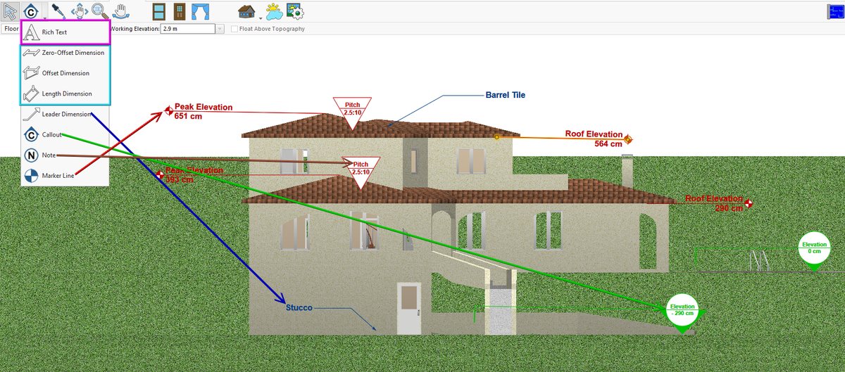
Select any line or text you have added to change its appearance on the Draw Style tab.
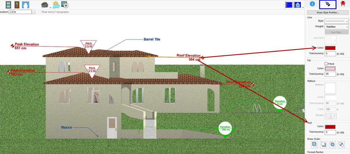
Step 3: Repeat for each side and print
Annotations belong to the view they were added in. When you switch to another side, add that side’s annotations too. Then print or export each elevation.
For a view through the building rather than of its outside, see how to create cross sections.